This is a tutorial to do building spatial analysis using depthmapX (link) or UCL Depthmap (link). The tutorial is based on an autocad drawing of a gallery that could be downloaded here (link). You could use this tutorial on your own building project drawn in a CAD or GIS package exported to a dxf format.
Your first building plan
1. Open depthmapX : double click on depthmapX.exe icon to open the software
2. Open new file window : File – New – Blank pane appears
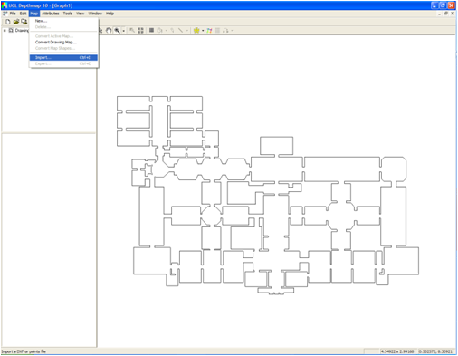
3. Import Dxf : Map – Import – Open your dxf file (A)
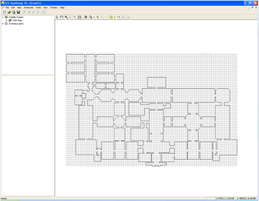
3. Define grid for analysis : Tools– Visibility – Set Grid – use default grid size or set a smaller grid size where every space is covered by at least one cell including corridors. Different grid sizes are appropriate for different buildings. It is recommended that you try a good range of grid sizes. (B)
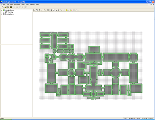
4. Fill the grid area for analysis : Click the fill icon in toolbar ![]() – Move the cursor on the spaces that needs to be analysed – right click – continue until all spaces that needs to be analysed are filled (C);
– Move the cursor on the spaces that needs to be analysed – right click – continue until all spaces that needs to be analysed are filled (C);
5. Create visibility graph : Tools– Visibility – Make Visibility Graph – Press OK.
You now have a visibility graph (D)
Your first building analysis
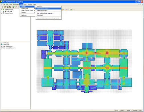
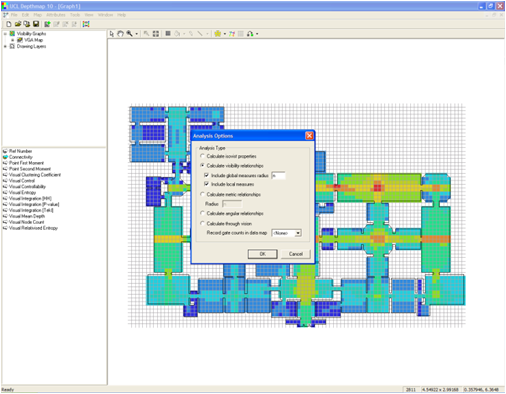
6. Run visibility graph analysis : Tools– Visibility – Run Visibility Graph Analysis (E);
7. Visibility analysis options : Select Calculate visibility relationships – tick Include global measures radius – Click OK.
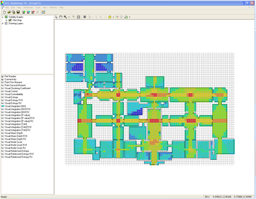
8. You now have a VGA plan (F), coloured in terms of the syntactic values, such as visual integration.
For more advanced instructions please see the depthmapX website. (link)


